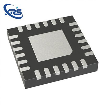
What are the input requirements of a Timing IC?
Leave a message
Hey there! As a Timing IC supplier, I've been getting a lot of questions lately about the input requirements of these nifty little chips. So, I thought I'd take a few minutes to break it down for you in a way that's easy to understand.
First off, let's talk about what a Timing IC is. In a nutshell, it's an integrated circuit that's designed to generate, distribute, and control timing signals. These signals are crucial for the proper functioning of all sorts of electronic devices, from smartphones and computers to industrial equipment and automotive systems.
Now, when it comes to the input requirements of a Timing IC, there are a few key factors to consider. Let's dive into each of them.
Power Supply Input
One of the most basic input requirements for a Timing IC is a stable power supply. Just like any other electronic component, a Timing IC needs a certain amount of voltage and current to operate correctly. Most Timing ICs are designed to work with a specific range of power supply voltages, typically between 1.8V and 5V.
It's important to make sure that the power supply you're using can provide a clean and stable voltage. Any fluctuations or noise in the power supply can cause the Timing IC to malfunction or produce inaccurate timing signals. To achieve this, you might need to use a voltage regulator or a decoupling capacitor to filter out any unwanted noise.
Clock Input
The clock input is another critical requirement for a Timing IC. This is the signal that the IC uses as a reference to generate all of its other timing signals. The clock input can come from a variety of sources, such as a crystal oscillator, a ceramic resonator, or another clock generator.
The frequency and stability of the clock input are crucial. The frequency determines the speed at which the Timing IC operates, and any variations in the frequency can lead to timing errors. For example, if you're using a Timing IC in a communication system, an inaccurate clock frequency can cause data transmission errors.
When choosing a clock source, you need to consider its accuracy, stability over temperature, and phase noise. A high - quality crystal oscillator is often a good choice because it can provide a very stable and accurate clock signal.
Control Inputs
Many Timing ICs also have control inputs that allow you to configure their operation. These inputs can be used to enable or disable certain functions, select different output frequencies, or adjust the phase of the output signals.
For example, some Timing ICs have a reset input that you can use to initialize the IC and set it back to its default state. Others might have a frequency selection input that lets you choose between different output frequencies.
The control inputs are usually digital signals, which means they can be either high (logic 1) or low (logic 0). You need to make sure that the signals you're applying to these inputs are within the specified voltage levels for the Timing IC.
Input Impedance
Input impedance is another factor that you need to take into account. The input impedance of a Timing IC determines how much current it draws from the input source. A high - input impedance means that the IC draws very little current, which is beneficial because it doesn't load down the input source.


On the other hand, a low - input impedance can cause problems, especially if the input source has a limited current - driving capability. If the input impedance is too low, it can cause a voltage drop across the input source, which can affect the accuracy of the input signal.
Real Time Clock IC, Clock Synthesizer IC, and Clock Buffer IC
Now, let's take a quick look at some specific types of Timing ICs and their input requirements.
Real Time Clock IC is designed to keep track of the current time and date. In addition to the power supply and clock input, it usually requires a backup power source, such as a battery. This is because the Real Time Clock IC needs to continue running even when the main power supply is turned off.
Clock Synthesizer IC is used to generate multiple clock signals with different frequencies from a single input clock. It often has more complex control inputs that allow you to program the output frequencies. You need to provide accurate control signals to these inputs to get the desired output frequencies.
Clock Buffer IC is used to distribute a clock signal to multiple loads. It typically has a high - input impedance to minimize the loading on the input clock source. The input requirements for a Clock Buffer IC are mainly focused on the quality and stability of the input clock signal.
Conclusion
So, there you have it! The input requirements of a Timing IC are diverse and crucial for its proper operation. From a stable power supply and accurate clock input to well - defined control inputs, every aspect plays a vital role in ensuring that the Timing IC can generate reliable and accurate timing signals.
If you're in the market for Timing ICs and have any questions about their input requirements or which type of IC is right for your application, don't hesitate to reach out. We're here to help you find the perfect solution for your needs. Whether you're working on a small consumer device or a large - scale industrial project, we've got the expertise and the products to support you. Let's start a conversation and see how we can work together to make your project a success.
References
- "Integrated Circuit Design: From Layout to Test" by R. Jacob Baker
- "CMOS Circuit Design, Layout, and Simulation" by R. Jacob Baker
- Technical datasheets of various Timing ICs from leading semiconductor manufacturers.


